When designing FPGAs, code quality is essential to staying on schedule, avoiding design iterations and worse, bugs found in production. This is especially true when it comes to high reliability applications such as automotive, space and medical devices where bugs can be extremely expensive or impossible to fix. But just what makes RTL (VHDL or SystemVerilog) quality code? The answer is, well, there isn’t just one thing that makes for quality code. It’s a combination of considerations from readability to architecture choices.
In Part 1 of this blog series, I focused on readable and maintainable RTL code, highlighting some best practices. Part 2 will now deep dive into Finite State Machine (FSM) architectures and coding guidelines. Finally, part 3 will focus on the challenges concerning multiple Clock Domains.
FSM Architectures and Coding Guidelines.
Before we focus on a specific architecture, let’s recap the different methods or protections we might use on our state machine and what we are protecting against. If a single-event upset (SEU, a radiation- induced change in the bit in one flip-flop) occurs in a state register, the FSM that contains the register could go into an erroneous state or could “hang,” by which is meant that the machine could remain in undefined states indefinitely or requiring a reset of the FSM as the only way to recover.
Obviously, in many applications, this is not acceptable or is completely impractical. We want the state machine to be able to either continue operating (tolerance) or detect a failure and fail safe (detection).
To ensure reliability of the state machine, the coding scheme for bits in the state register must satisfy the following criteria:
- 1. All possible states must be defined
- 2. A SEU brings the state machine to a known state
- 3. There is no possibility of a hang state
- 4. No false state is entered
- 5. A SEU exerts no effect on the state machine
Tolerance
When it comes to tolerance there are two mechanisms we can use:
- Triple Modular Redundancy (TMR) — With TMR three instantiations of the state machine are created, and the output and current state are voted upon clock cycle by clock cycle. TMR is a good approach, but it does require three implementations and ensuring physical separation of the three implementations to ensure only one FSM is corrupted. For more on TMR I recommend that you view Xilinx Isolation Design Flow. This documented flow can be especially useful for ensuring physical separation in the chip.
- Hamming Three Encoded — With a Hamming three encoded state machine, each state is encoded with a hamming distance of three between them. This prevents a SEU from changing between valid states, as the SEU can only flip a single bit. In a Hamming three, each state has several adjacent states which also cover the possible states to which a SEU could change the Hamming three state. This adjacent state behaves the same as the original state, hence allowing the state machine to tolerate the SEU and keep operating. It does, however, mean the number of states declared is large. For a 16 state FSM encoded sequentially, seven bits are needed to encode the 16 states separated by a Hamming distance of three. This means there are N * (M+1) states required, where N is the number of states and M is the register size.
Both the TMR and Hamming three structures require considerable effort from the design engineer unless the structure can be implemented automatically by the synthesis tool.
Detection
When it comes to detection, the structures used are considerably simpler:
- Hamming Two (sequential + parity) — This method encodes the state with a Hamming distance of two. Should a SEU occur, the error can be found using a simple XOR network and the state machine can be recovered to a safe state to recommence operation.
- Default Case / When Others —This method uses the Verilog default or VHDL when others to implement a recover state. This does require that the synthesis tool does not ignore the default case or when others, and that the user does not define them as null or do not care.
Hamming Two is the best compromise in terms of size, speed, and fault-tolerance and is preferred over both binary and one-hot state machine encoding for high reliability designs. Hamming Three encoding is the best fault-tolerant to single faults and, therefore, preferred when ultimate reliability is required in a critical application, however it is slower and larger than other implementations.
Static Verification of FSMs
As mentioned earlier, for highly reliable FSMs, all possible states must be defined and there must be no possibility of a hang state.
Functional verification of an FPGA’s RTL requires a considerable simulation effort to achieve code coverage (branch, path, toggle, condition, expression etc.). To achieve a high level of coverage the simulation must test several boundary and corner cases to observe the behavior of the unit under test and ensure its correctness. This can lead to long simulation runs and significant delays between iterations when issues are detected. Of course, issues found in simulation can range from functional performance such as insufficient throughput to state machine deadlocks due to incorrect implementation during the coding process.
This is where static analysis tools such as the Visual Verification Suite from Blue Pearl Software can be wonderfully complementary to functional simulation and can help save considerable time and effort in the verification stage, when code coverage is being investigated.
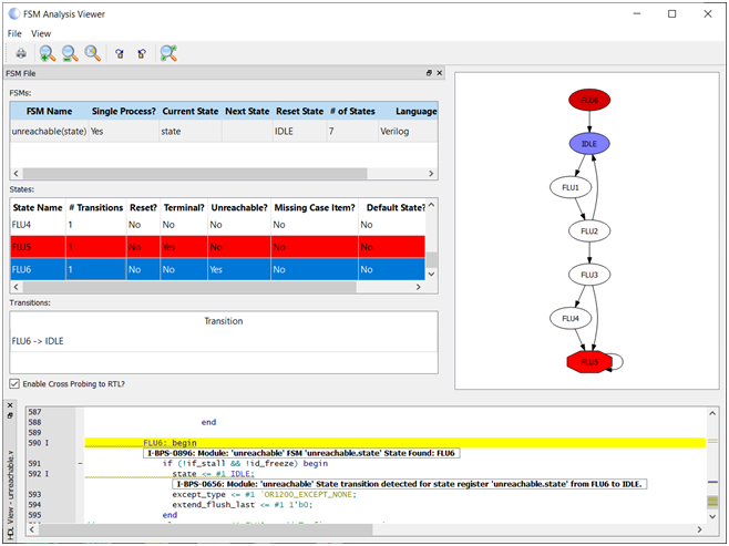
Static analysis enables functional verification to be started with a much higher quality of code, reducing iterations late in the verification cycle. In addition, static analysis typically also runs in tens of seconds to minutes compared to long running simulations. The Visual Verification Suite provides an FSM viewer and reports that help pinpoint any issues, up front, as you code.
Many of the suite’s predefined rules focus upon the structural elements which may be incorrect in the design such as:
- Unnecessary events – These are unnecessary signals included in the sensitivity list. Such inclusion will lead to simulation mismatch and add complexity to achieving code coverage.
- If-Then-Else Depth – This will analyze the If-Then-Else structures to identify deep paths which may impact timing performance and throughput when implemented.
- Terminal State – This is a state in a state machine which once entered has no exit condition. Finding this prior to simulation can save wasted simulation time.
- Unreachable State – This is a state in a state machine which has no entrance condition. Finding this prior to simulation can again save considerable simulation time.
- Reset – This ensures each flip flop is reset and reset removal is synchronous to the clock domain of the reset. Several in-orbit issues have been detected relying upon the power-on status of registers and as such reset for all flip flops is best practice.
- Clocking – Clocking structures are also analyzed to ensure there is no clock gating or generation of internal clocks.
- Safe Counters – Checks to counters ensure that terminal counts use greater than or equal to for up counters and less than or equal to for down counters. This ensures single event effects have a reduced impact on locking up counters.
- Dead or unused code – Analyzes and warns about unused or dead code in the design. This can be removed prior to functional simulation and reduces head scratching when code coverage cannot be achieved.
Visual Verification Suite, used early and often in the design process as opposed to as an end of design/sign-off only tool, significantly contributes to design security, efficiency, and quality, while minimizing chances of field vulnerabilities and failures.
To learn more about the Visual Verification suite, please request a demonstration, and check back for Part 3, the challenges around multiple Clock Domains.