All engineers know the earlier we identify an issue in our design, the easier and less costly it is to correct. We also know some issues are easier than others to identify. The worst kind are those which are intermittent and manifest late in the test regime or, even worse, in the field. These late arising issues lead to many long hours and stress in the engineering team as we try to address the root cause.
While these root causes may be varied, we can group them together into several likely classes which may be the root cause. These include:
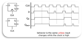
- Missing Assignments – Missing assignments arise from how we write the code, for example an IF check not having a corresponding ELSE or missing a CASE statement. Structures such as this will result in different behaviour depending on the synthesis tool, inferring either latches or registers. The latch will of course behave differently which impacts portability and may result in issues in corner cases, which are hard to track down.
- Clocking – Modern designs contain several clock domains. Of course, information needs to be shared between these domains. Incorrect synchronisation of data and signals between clock domains can result in metastability and corrupted data. In some systems this incorrect data can be catastrophic. Most engineers will use two stage synchronisers and FIFOs to transfer data safely however, due to the complexity of designs, signals can slip through the net and be unsynchronised. One example which can be hard to find is using a FIFO status signal e.g. Full or Empty on the wrong clock domain. This will lead to intermittent behaviour which might not be found until late in the product life cycle.
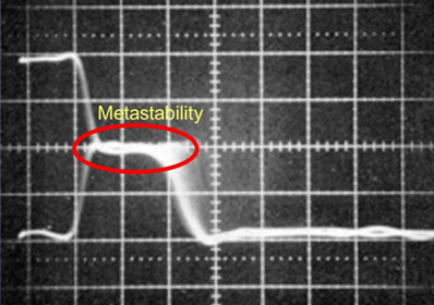
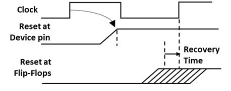
- Reset – Incorrect handling of asynchronous reset release or de-assertion can lead to metastable events if reset release changes during the flip flop’s hold or set up time. As the relationship between the reset and clock is asynchronous, this relationship will change each time the board is powered. We also need to consider the internal routing delays of the reset signal; what may look good at the pins is still an issue at the flop as delays in routing can also introduce metastability.
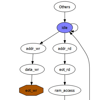
- Finite State Machine (FSM) Behaviour – FSM are the heart of our designs; they are how we implement sequential control structures in our FPGA and ASICs. The more complex the FSM, the harder it is to visualise and ensure all states are reachable and that a transition to a state is not terminal. If state machines have inadvertent terminal states, the state machine will lock up and be unrecoverable unless power cycled or reset.
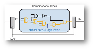
- Longest Path – Long combinatorial paths between registers impacts the maximum frequency with which we can achieve timing closure. This can also cause issues during the place and route when paths which fail timing are incorrectly reported as being the longest path (In reality they are the longest paths failing timing).
When we generate our designs, we are of course aware of these issues and attempt to mitigate these using independent code reviews and coding standards. However, as designs get larger and more complex it is hard to detect and verify them all.
This is where tools such as Blue Pearl Software’s Visual Verification Suite comes into their own. Let’s take a quick look at how we can use the suite of tools to identify and address these issues.
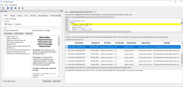
When we load a design into the suite, the design is subject to several (configurable) load checks, which check for missing assignments and reset behaviour along with several other checks. These load checks enable us to identify issues such as asynchronous reset synchronisation, missing assignments and undriven logic.
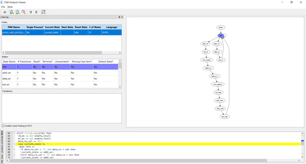
To ensure our FSMs behave as expected, we can use the FSM viewer to visually verify the behaviour of the state machine. This is to ensure that each state has entry and exit points and that no state becomes a terminal state from which once entered there is no exit.
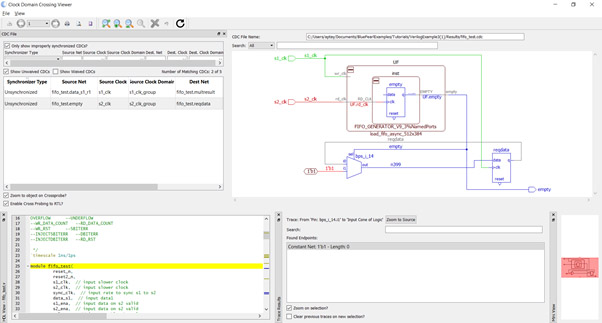
Of course, at the heart of suite is the Clock Domain Clocking (CDC) analysis capability, which enables us to identify Clock Domain Crossings which are not correctly synchronised. Once identified we can quickly and easily implement a solution which addresses the identified issue. As in the example below where the empty flag is used in conjunction with the write clock without synchronisation, this will at times result in a very hard to find intermittent metastability issue.
Now we have outlined some of the key design challenges which can impact our design late in the development cycle or even worse in the field and how we can identify and correct these. Over the next few blogs we are going to take a deeper look at how we can use the suite to identify and correct these issues.
If, however, you cannot wait, why not join me at DAC 2019 in Las Vegas where I am running a lunch and learn on Monday at the Blue Pearl Software booth #345. I will be demonstrating how we can use Visual Verification Suite to find and correct these design issues and more.