When it comes to crossing clock domains it is best, if possible, to implement the crossing using registers which are located close together and have small set up and hold windows. In short, our register structures used for clock domain crossing should be optimized for signals which may go metastable.
In our Xilinx designs this means we need to use either the HARD_SYNC primitive, or alternatively if our CDC issues are more complex, one of the Xilinx Parameterized Macros (XPM). Xilinx Parameterized Macros can be used to implement CDC, FIFO and BRAM solutions in your design. When it comes to working with BRAM and FIFO, unlike using the BRAM/FIFO generator which uses black boxes in synthesis, XPMs are not black boxed and therefore enable the synthesis tool to make better timing and resource estimates. They also allow for faster simulation than when using the BRAM/FIFO generator. We can use these libraries in 7 Series, UltraScale and UltraScale+ families.
Of course, we are interested in the seven-clock domain crossing (CDC) capabilities provided by XPM. These are:
- Single Bit Synchronizer – Synchronizes a single bit vector between clocks.
- Asynchronous Reset Synchronizer – Synchronizes an asynchronous reset to the destination clock. Reset assertion is asynchronous while the reset removal will always be synchronous and safe for the destination clock.
- Gray Code Synchronizer – Synchronizes a data bus between source and destination clocks, using Gray coding. Using this implementation, the input can only increment or decrement by one between values, making it useful for counters.
- Handshake Synchronizer – Synchronizes a data bus between source and destination clocks using handshaking of signals.
- Pulse Synchronizer – Synchronizes a pulse of any width (one source clock cycle or wider) from the source domain to the destination domain.
- Single Bit Synchronizer – Synchronizes a single bit from source to destination domain.
- Synchronous Reset Synchronizer – Synchronizes a synchronous reset to the destination clock domain. This both asserts and de-asserts the reset synchronously, unlike the Asynchronous reset macro.
Let’s look at how we can create a simple example using XPM CDC functions and verify the crossings as safe using Blue Pearl Software’s Visual Verification™ Suite.
The code itself for this demonstration is quite simple and will contain two clock domains. The first clock domain will contain a simple counter which counts to a terminal value. This counter can be restarted by a restart signal and reset asynchronously.
Both the restart signal and asynchronous reset are contained within the second clock domain and as such require crossing from one clock domain to another. To perform the clock domain crossing I used the Single Bit Synchronizer and Asynchronous Reset Synchronizer.
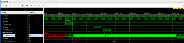
Using the Xilinx Vivado™ Design Suite to simulate the design (available on my GitHub), you can see the asynchronous reset and start signals being retimed by the XPM CDC Macros.
When we load this design into the Blue Pearl Visual Verification Suite we can confirm that we have correctly and safely crossed the clock domain.
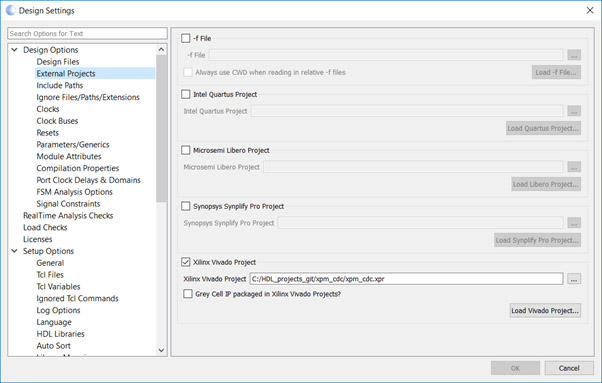
The first thing we need to do in VVS is the import the Vivado project. We can do this using design settings and selecting the external projects dialog and pointing VVS to our Vivado project.
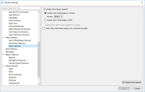
We also need to select the version of the tool we are using on the FPGA Vendors dialog
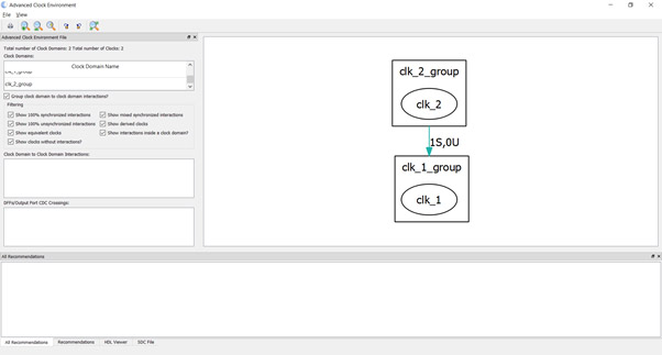
Once that is complete, we can load the design. However, before we run the full CDC analysis, we may want to explore the Advanced Clock Environment which shows relationships between clocks and gives a preliminary indication of whether signals are synchronized or not. In this case we should see we have one signal which is passing from clock domain two to one and is synchronized.
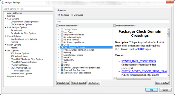
To ensure the clock domain crossings are correct we run the CDC analysis. To do this we need to first ensure that the CDC analysis checks are enabled in the analysis settings.
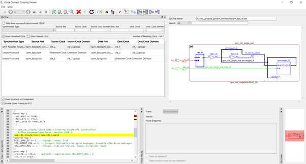
Running this analysis and then opening the Clock Domain Crossing Viewer will show three crossings. If you only see two, ensure the “only show improperly synchronizes CDCs?” check box is NOT checked.
You will then be able to see three crossings, the first a correctly implemented crossing from clock domain two to one. Cross probing to the source code will highlight the XPM instance.
The remaining two are associated with the input and output signals as the clock is not defined for those signals.
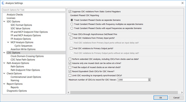
There are two ways we can address this issue. We can use an SDC file to associate the inputs with a clock domain. Alternatively, we can uncheck the “Find CDC Violation on Primary Input/Output ports” check box option.
When we rerun the analysis now, we will see only one properly synchronized crossing from clock two to clock one.
Now we understand how we can use XPM CDC structures to perform safe clock domain crossings in our Xilinx devices and that VVS will pick up and identify XPM CDC structures correctly. This enables us to focus on clock domain crossings which might have been missed in the VVS CDC environment.
You can obtain the Vivado project and design files here if you wish to experiment with XPM and VVS.
To read more about the Xilinx / Blue Pearl integration in our white paper.