State machines are at the heart of our designs. They enable us to implement sequential structures in a parallel programmable logic world. We use them to implement control structures and communication protocols, however complex state machines design can also significantly slow down our development due to the challenges associated in debugging issues, epically if only using simulation for verification.
Let’s look at some simple steps we can take when implementing state machines to reduce the number of potential issues introduced, along with how to analyze them using Blue Pearl’s Visual Verification™ Suite to accelerate debug before simulation.
When developing a state machine, it is good practice to ensure our design uses the following factors:
- Implement all the functionality in a single clocked process. This prevents the implementation of latches or un-synthesizable combinatorial logic constructs. It also ensures all outputs from the state machine are clocked. A single process state machine also prevents mixed decoding of the present and next state in the design, as there is only one state. Single process state machines are also easier to debug if necessary.
- Ensure the state machine has a clearly defined reset state. When defining this state, do not rely on positional association of the reset state in the state definition.
- Decouple as much functionality as possible from the state machines. Do not decode large buses or counters within the state machine body. In place of this, pass single bit inputs and outputs from the state machine to start counters or indicate that the counter has reached its terminal value. This decouples large elements of logic from the state machine implementation, allowing for a better implementation and improved timing.
- If the state machine does not use a power-of-two states and the application is a high reliability or mission critical implementation, ensure that the unused states are correctly addressed so the state machine does not lock up if an unused state is entered due to noise or single event effects. Correctly addressing unused states means ensuring that for each unused state there is a recovery to a known state so operation can continue.
Once we have implemented our state machine design, the next stage is to integrate it within the larger design and then analyze the design using Visual Verification Suite.
Analyzing our state machines in Visual Verification Suite is very simple and performed as part of the load process. Before we load our design and perform the FSM analysis, we need to first configure the analysis.
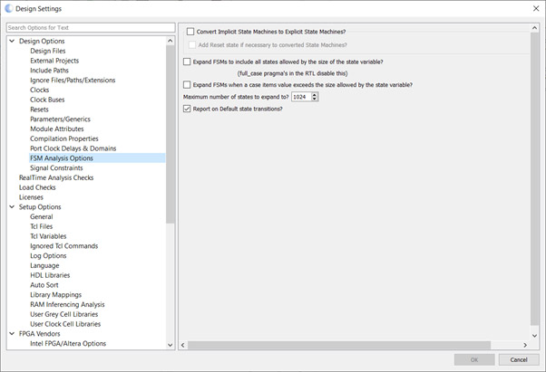
The first step is to define the FSM Analysis options. Here we can configure what analysis is performed. One of the crucial options is the conversion of implicit state machines to explicit state machines; without this an implicit state machine may not synthesize.
If you are not familiar with implicit state machines, they are the state machines which are defined in a more traditionally software style consisting of loop, branches and wait states.
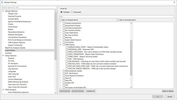
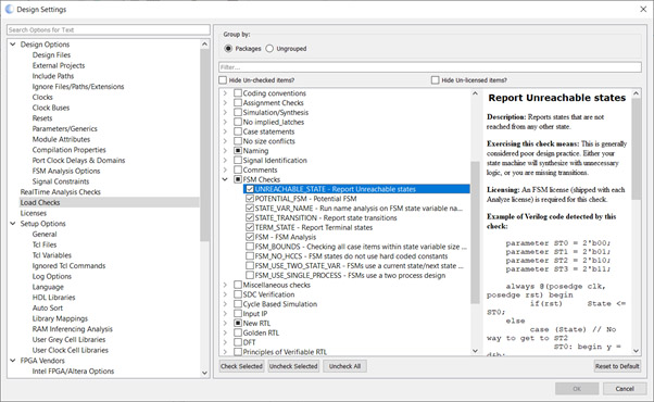
Once the FSM analysis is correctly configured, we can define further checks on the FSM under Load Checks. Here we can define which rules we wish to use to check our state machine, such as checking that the state machine is implemented using a single or two process structure as required by our design rules (FSM_USE_SINGLE_PROCESS and FSM_USE_TWO_STATE_VAR).
We are also able to check to ensure there are no unreachable states or terminal states included within the design. For safety critical / high reliability applications, the ability to ensure that unused states are correctly addressed in the design is very important, since once entered they become terminal states if not correctly addressed.
Terminal states can occur if unused state states are incorrectly addressed, or due to design error where a state is entered but the logic to exit that state is not implemented correctly.
With the options configured in line with the design standards, the design settings window can be closed and the design loaded, which runs the analysis.
Once the design is loaded, we can view the FSM analysis results. These are available in both as messages in the results view, and graphically in the FSM Analysis View.
To demonstrate the capabilities of the FSM analysis we will use the unmapped state example, which can be found under the help menu.
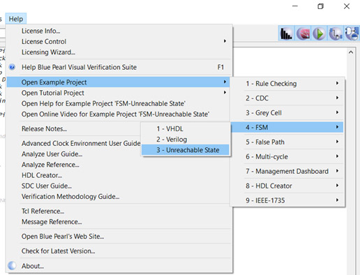
This will load in an example Verilog file which contains a state machine which has a design issue.
Before the design is loaded and analyzed, click on the design settings to see how the FSM analysis for this example is configured.
Loading the design will perform the FSM Analysis, and results will be available under the “View Results” option and the FSM Analysis Viewer.
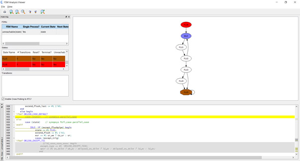
Looking at the FSM Analysis Viewer we will notice that this design has a terminal state for state five, which results in state six being unreachable. Both have colors (brown and red respectively) to show the states where issues exist.
Having identified this issue in the FSM Analysis Viewer we are then able to correct the RTL source to behave as intended.
This ability to enforce good design practice and analyze the FSM behavior quickly enables us to identify issues earlier in the RTL source code, which can save time in development process as issues are identified before simulation and synthesis.