The capabilities for Blue Pearl’s Visual Verification Suite are well known for Lint, Clock Domain Crossing Analysis and Design Management. However, there are several capabilities in the tool which are easily overlooked but nevertheless provide the designer with significant benefits, let’slook at five of these.
- 1. Text Reports – Along with the linting and messages which result from the structural analysis checks. The suitealso enables designers to generate additionaltext reports on the design. These text reports provide significant detail on the objects structure, design resources, generic and parameter settings and so on aboutthe design. This information is particularly useful if you are trying to understand a legacy design, especially when combined with the dependency viewer. However, usefulness of the text reports is not limited to just information which helps us understand the design. It also includes information which can help us gain better performance in the final design. One example of this being the IF/THEN/ELSE length report.Understanding the IF/THEN/ELSE depth enables the designer to identify areas of the design where optimizations can be made to ensure timing performance is achieved.

Enabling Text Reports

IF/THEN/ELSE Depth - 2. Schematic Viewer – The schematic viewer is ideal when we are trying to isolate issues raised in the linting structural checks, CDC and SDC analysis. The schematic viewer can also be used to visualize a legacy design to understand the interconnection between modules and most importantly clocking and reset structure.

Clock Tree View

Reset Tree View
Schematic Actions for a selected element - 3. Path Analysis – Timing closure is one of the most time-consuming elements of the logic design process. Often,when using programmable logic, we need to wait for the vendor design tool to complete its implementation before we know of any timing issues. This of course, can take several hours and is often an iterative process. One of the key design structures which impacts timing performance is the path length, that is the number of logic elements between flip flops. The Visual Verification Suite’s Analyze RTL tool elaborates the RTL design and indicates the long paths between flip flops. This allows the designer to act, to correct before implementation. Using such analysis can save the design engineer significant time in the implementation stages of the project.

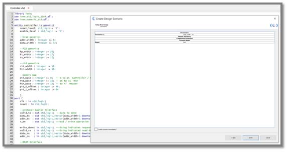
Path Analysis between two registers - 4. Design Scenarios – When we design our RTL modules, we want them to be as reusable as possible, saving design time. To make our designs as flexible as possible we often use generics or parameters in our RTL to enable different final implementations of the IP core in the FPGA or ASIC. Within the suite, design scenario enables us to create solutions with a different setting of the generics and parameters within our designs.
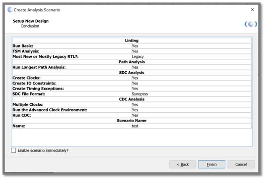
- 5. Analysis Scenarios – Similar to the design scenario, analysis scenarios allow us to change the settings currently used by Analyze. The benefit of changing Analyze settings in this manner is the original settings remain unchanged while we observe the impact of making the changes to the checks.If they are accepted, we can add them into the main settings. Alternatively, we can use scenarios to run different checks on files depending upon the required level of check.
Both the Design and Analysis scenarios, once completed, create a new option under the design scenarios menu which can be used to enable that scenario. If you need to change the configuration of the scenario once it is enabled,just use the “design settings” as we would do for a normal scenario.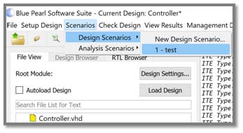
Hopefully, you can see the benefits these five capabilities of Blue Pearl Software’s Visual Verification Suite can bring to your ASIC and FPGA verification.