User Grey Cell™ methodology from Blue Pearl Software
Growth of IP-based designs
As design complexity escalates, designers increasingly rely on commercial or existing IPs to meet project deadlines rather than designing everything from scratch. According to Semico Research, over the next couple of years, the number of IPs per design will increase from an average of 50 to a staggering 180. The difficulty of IP integration and design verification will undoubtedly grow exponentially. Even today, many design teams complain that it takes too long for integration and verification using existing methodologies.
Leading cause of metastability
Designs today integrate components/IPs from many sources that operate with independent clocks with different frequency and phase relationship. This is done to bring data into the design from different sources or to change frequency in order to optimize power. The added complexity of disabling many logic cones means verification engineers need to be more vigilant.
Whenever there are setup or hold time violations in any flip-flop, it can enter a state where its output is unpredictable. This state is known as metastable state. It could well be that the flip-flop will settle in a known state. But due to dependencies on thermal and induced noise, one cannot be certain on the time it takes to settle. The likelihood of a functional failure due to metastability increases with clock frequency.
When components or IPs with different clock phase/frequency interface, the receiving logic flip-flop may violate setup or hold time causing the output to not settle to a stable “1” or “0” state. This metastable state can get propagated through the design as erroneous states causing functional failures. Hence it is important for designers to find portions of their designs where CDC can occur. Designers then insert logic to greatly reduce the likelihood of propagating erroneous data due to metastable signals.
Failure of the Black Box methodology
As discussed earlier, the required components/IPs come from varied sources. They could be acquired in synthesizable RTL format, protected IP format, simulation models, or non-synthesizable formats. If the IP is in the form of a synthesizable RTL, then it is relatively straightforward to do CDC analysis through it. However, for the other formats, the IPs have traditionally been treated as black boxes i.e. the analysis will not use any knowledge of the internals of the IP. In a black box methodology, the CDC analysis will stop at each IP boundary and treat it as an end point with no relationship whatsoever with what’s inside the IP.
As designers rely more and more on IPs, the number of black boxes included in the analysis is increasing. Thus, the risk of missing critical CDC issues grows. Moreover, since the IPs are instantiated in hierarchical designs, it quickly becomes impossible to manually trace and decide whether a particular black box can cause a CDC issue.
What is a User Grey Cell™?
A User Grey Cell™, as depicted in Figure 1 below, contains more information than a black box. The User Grey Cell™ reduces the amount of information in the complete proprietary RTL design to what is sufficient for CDC analysis.
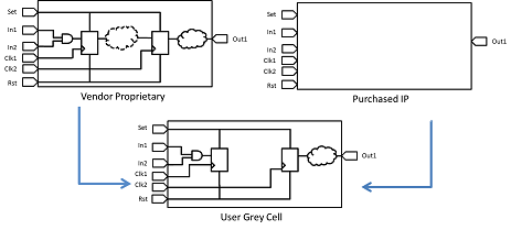
Figure 1: User Grey Cell™ representation
The User Grey Cell™ provides clocking and register information that allows for an accurate CDC analysis. When creating a Use Grey Cell™, the user needs to specify only those ports that are relevant to the current design, rather than specifying all the ports.
A User Grey Cell™ is specified in xml format. A default set is supplied in the Blue Pearl Software distribution package, and a designer can create new User Grey Cells that will be recognized by the software. Some key elements of the xml content include:
- Cell attributes: This allows for matching between entity and architecture. Specify the name of the module and some of its properties, such as whether you are creating a synchronization cell.
- Input and Output pins: Specification of a regular input or output pin requires either notation of a clock pin, in which case a DFF is inferred, or that the pin is asynchronous. You also have the option of specifying a reset pin along with a clock.
- Clock pins: An inferred DFF for an input or output must be matched with a specified clock input pin. A clock output pin represents a new clock domain.
- Reset pins: An inferred DFF for an input or output can be matched with a specified reset pin, as noted above.
- The xml syntax is also flexible enough to allow for equation definition and parameterization of the pins.
In Figure 2 below, a simple User Grey Cell™ xml is shown with the definitions of the input, output, reset, and clock pins.
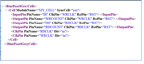
Figure 2: User Grey Cell™ in xml
Benefits of a User Grey Cell™
So far, we have discussed how the User Grey Cell™ enables CDC analysis beyond what is possible with just a black box methodology. Some other benefits, which may not be immediately evident include:
• Since different models for different bus width are not required, the use of parameterizable ports greatly reduces the number of models required, especially for complex components such as memories and FIFOs.
• Because clock and reset relationships for each pin are specified in the User Grey Cell™, the complexity of CDC setup and analysis is greatly reduced. This is true especially for complex cores like DDR or PCI express that may have internal reset, clock network and synchronizers.
• A User Grey cell™, when defined as a synchronization cell, allows for that cell to be used as a synchronizer in the context of the design. A CDC analysis can be run with this User Grey Cell labeled as synchronizer.
Sample Result using the User Grey Cell™ for a generated FIFO
For illustration purposes, we use a loop back fifo design to show the usage of a User Grey Cell™. The fifo is generated from Xilinx CoreGen™. Since the fifo is generated, there is no RTL description of the functionality. While parsing the design, the fifo will be represented by a black box unless the user specifies the path to the User Grey Cell™ model.
When the fifo is treated as a black box during the CDC analysis, no CDC issues are found. This can give a false sense of confidence leading the designer to believe that the design is free from any CDC errors. However, when the User Grey Cell™ model is specified, CDC analysis shows multiple CDC issues as shown in Figure 3 below
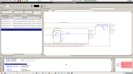
Figure 3: CDC issues found when using the User Grey Cell™ model
What’s the Take Away?
Designers who are frustrated with or who have been burned by unexplained chip failures caused by metastability issues now have an alternative to the black box method of verification. Using Blue Pearl’s relatively easy to use User Grey Cell™ methodology, the chances of missing the metastability-causing CDC problems can be significantly reduced.